
")
CERN and CMS engineers and technicians have installed the first two of nine required next-generation carbon dioxide (CO2) cooling plants in the underground Service Cavern of the CMS experiment in Cessy, France, as well as two of the accumulators. The new - and more powerful - system will replace a legacy primary cooling circuit that employs synthetic refrigerant, thereby significantly improving the environmental impact of the full detector cooling chain.
The cooling plants, weighing about 5 tonnes each, are essential components of Hi-Lumi CMS, due to go into operation in 2030. Parts of the detector will need to be kept extremely cold - at temperatures below -30 °C. To achieve this, the cooling plants will extract up to 550 kW of heat in total from three new CMS sub-detectors in the Hi-Lumi build – the Tracker, MIP Timing Detector, and High-Granularity Calorimeter – while maintaining stable temperatures, and eliminating synthetic refrigerants with high global warming potential from the full cooling chain. This is a significant development compared to the present CO2 system, which removes up to 10 kW from the pixel detector at -20 °C, and relies on synthetic refrigerants for its primary circuit.
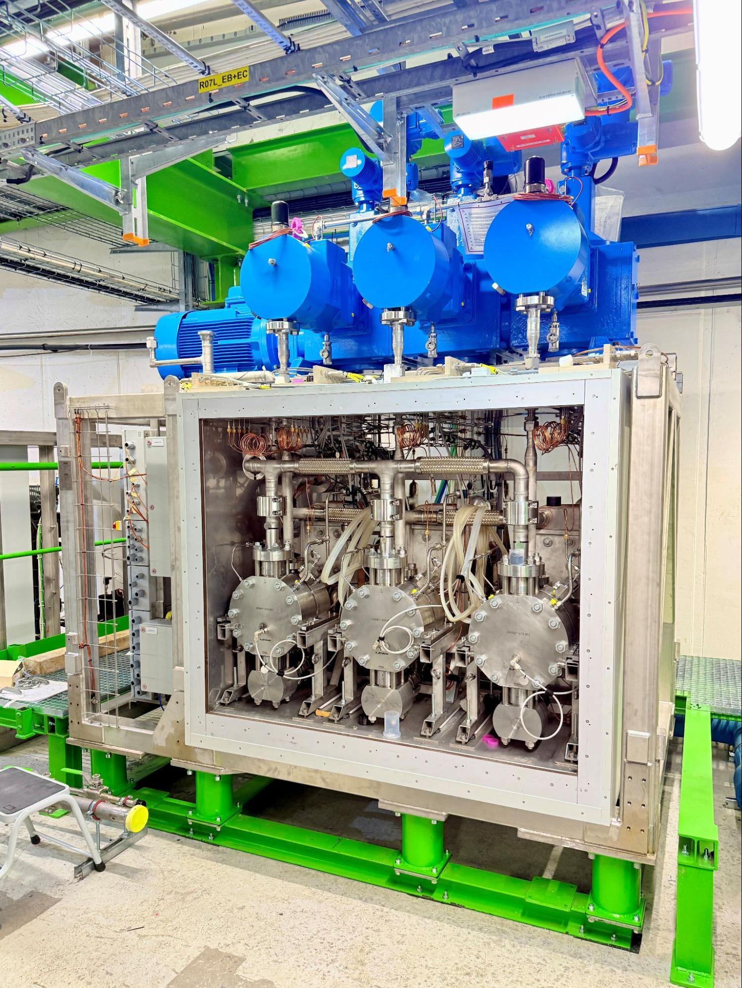
Above: CO2 cooling plant in the CMS service cavern. (Photo by Jérôme Daguin)
In comparison, CMS' new CO2 cooling system delivers a huge order-of-magnitude increase in cooling capacity while approaching the temperature limits of CO2. It is the culmination of an 8-year Research & Development effort by CERN's EP-DT group in collaboration with LPSC Grenoble and the CMS & ATLAS experiments. Although the systems' 2PACL (2-Phase Accumulator-Controlled Loop) process design can trace its origin from the AMS-02 experiment on the International Space Station, and through several CERN particle detectors, its new scale called for a major rethink of how it is implemented.
The enormous volume of CO2 needed by the new system required a 12-cubic-meter storage vessel on the surface of the experimental site, as well as innovations in industrial control systems to manage the fluid exchange with the underground systems. As only a few components from legacy CO2 cooling systems could scale to meet the new requirements, the development campaign also involved selecting and qualifying a long list of suppliers for this new class of system.
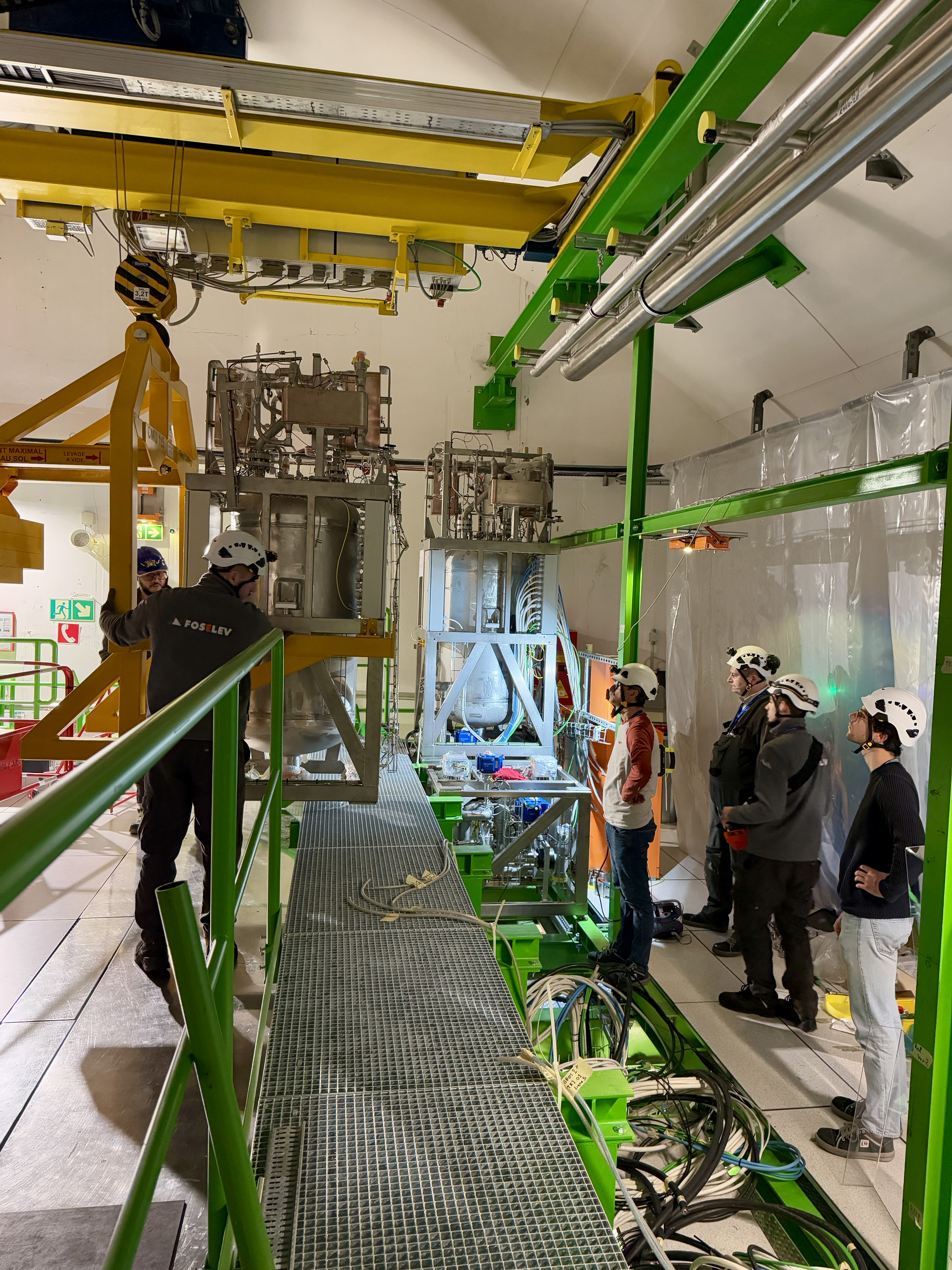
Above: Installation of the second accumulator. (Photo Jérôme Daguin)
Once fully installed, the 2PACL equipment in the CMS Service Cavern will comprise of nine cooling plants and eight accumulators – roughly 500-litre tanks that will control the cooling process by setting the pressure at which CO2 evaporates on the detector. From the service cavern, a network of several kilometres of coaxial transfer lines and several layers of manifolds will distribute the CO2 among thousands of evaporator pipes cooling the CMS detectors in the experimental cavern.
The underground equipment will exchange heat with a primary cooling circuit, and fluid with the surface storage vessel. These were designed by the CERN’s EP-DT and EN-CV groups in collaboration with the Norwegian University of Science and Technology, and then industrially developed by EN-CV. The primary circuit employs an innovative modification of a transcritical CO2 cooling process to produce stable cooling down to -53 °C and eject the heat produced by the detectors on the surface of the experiment.
The installation phase of the 2PACL cooling plants and related equipment is expected to continue through 2025, followed by an extensive commissioning campaign to dial in the new infrastructure. The distribution pipework will then be connected to the future detectors during Long-Shutdown 3, ready for action during the Hi-Lumi LHC era!